ใบงานวันที่31 มีนาคม 2560
รหัสนักศึกษา B5711826 ชื่อ นางสาวไอลดา พลพฤกษ์


}
}

-- MAX7219 registers
MAXREG_DECODEMODE = 0x09
MAXREG_INTENSITY = 0x0a
MAXREG_SCANLIMIT = 0x0b
MAXREG_SHUTDOWN = 0x0c
MAXREG_DISPTEST = 0x0f
1. ตองการแสดงขอความ

โค้ดในArduinoที่ใช้ในการรัน
#define NUMBER_OF_DEVICES 1
#define CS_PIN D8
LedMatrix ledMatrix = LedMatrix(NUMBER_OF_DEVICES, CS_PIN);
#define CS_PIN D8
LedMatrix ledMatrix = LedMatrix(NUMBER_OF_DEVICES, CS_PIN);
void setup() {
Serial.begin(115200); // For debugging output
ledMatrix.init();
ledMatrix.setIntensity(4); // range is 0-15
ledMatrix.clear();
ledMatrix.commit(); // commit send buffer to the displays
}
Serial.begin(115200); // For debugging output
ledMatrix.init();
ledMatrix.setIntensity(4); // range is 0-15
ledMatrix.clear();
ledMatrix.commit(); // commit send buffer to the displays
}
void loop() {
for (int i = 9999; i >= 0; i -= 7)
{ // ledMatrix.clear();
// ledMatrix.commit(); // commit send buffer to the displays
// delay(1000);
// Send2MAX7129(8, 1, 0);
// Send2MAX7129(7, 1, 0);
// Send2MAX7129(6, 2, 0);
// Send2MAX7129(5, 2, 0);
int xxx = i;
Send2MAX7129(4, xxx / 1000, 0); xxx = xxx % 1000;
Send2MAX7129(3, xxx / 100, 0); xxx = xxx % 100;
Send2MAX7129(2, xxx / 10, 0); xxx = xxx % 10;
Send2MAX7129(1, xxx / 1, 0);
delay(10);
}
}
//===================================================
//===================================================
void Send2MAX7129(byte SegPosition, byte Value, bool dotDigit)
{ const static byte charTable [] =
{ B01111110, B00110000, B01101101, B01111001,
B00110011, B01011011, B01011111, B01110000,
B01111111, B01111011, B01110111, B00011111,
B00001101, B00111101, B01001111, B01000111
};
Value = charTable[Value];
if (dotDigit == 1) Value |= 0x80;
digitalWrite(CS_PIN, LOW);
SPI.transfer (SegPosition);
SPI.transfer (Value);
digitalWrite (CS_PIN, HIGH);
Serial.print(Value);
}
if (dotDigit == 1) Value |= 0x80;
digitalWrite(CS_PIN, LOW);
SPI.transfer (SegPosition);
SPI.transfer (Value);
digitalWrite (CS_PIN, HIGH);
Serial.print(Value);
}
//===================================================
// ##SegPosition >> 87654321 ##SegData >> tabcdefg
//===================================================
void SendData2MAX7129(byte SegPosition, byte SegData)
{ digitalWrite(CS_PIN, LOW);
SPI.transfer (SegPosition);
SPI.transfer (SegData);
digitalWrite (CS_PIN, HIGH);
}
// ##SegPosition >> 87654321 ##SegData >> tabcdefg
//===================================================
void SendData2MAX7129(byte SegPosition, byte SegData)
{ digitalWrite(CS_PIN, LOW);
SPI.transfer (SegPosition);
SPI.transfer (SegData);
digitalWrite (CS_PIN, HIGH);
}
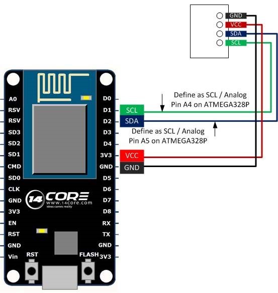
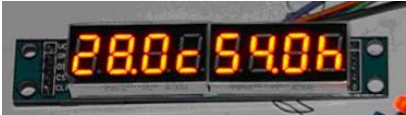
2. ใชArduino IDE ในการพัฒนาโปรแกรมใหอานอุณหภูมิจากเซ็นเซอรแลวแสดงผลที่
MAX7219_7Segment Display โดยมีรูปแบบดังรูป
โค้ดในArduinoที่ใช้ในการรัน
ClosedCube_HDC1080 hdc1080;
#define NUMBER_OF_DEVICES 1
#define CS_PIN D8
LedMatrix ledMatrix = LedMatrix(NUMBER_OF_DEVICES, CS_PIN);
#define CS_PIN D8
LedMatrix ledMatrix = LedMatrix(NUMBER_OF_DEVICES, CS_PIN);
void setup() {
Serial.begin(115200); // For debugging output
ledMatrix.init();
ledMatrix.setIntensity(8); // range is 0-15
ledMatrix.clear();
ledMatrix.commit(); // commit send buffer to the displays
Serial.begin(9600);
Serial.println("ClosedCube HDC1080 Arduino Test");
Serial.begin(115200); // For debugging output
ledMatrix.init();
ledMatrix.setIntensity(8); // range is 0-15
ledMatrix.clear();
ledMatrix.commit(); // commit send buffer to the displays
Serial.begin(9600);
Serial.println("ClosedCube HDC1080 Arduino Test");
// Heater off, 14 bit Temperature and Humidity Measurement Resolution
hdc1080.begin(0x40);
hdc1080.begin(0x40);
Serial.print("Manufacturer ID=0x");
Serial.println(hdc1080.readManufacturerId(), HEX); // 0x5449 ID of Texas Instruments
Serial.print("Device ID=0x");
Serial.println(hdc1080.readDeviceId(), HEX); // 0x1050 ID of the device
Serial.println(hdc1080.readManufacturerId(), HEX); // 0x5449 ID of Texas Instruments
Serial.print("Device ID=0x");
Serial.println(hdc1080.readDeviceId(), HEX); // 0x1050 ID of the device
}
void loop() {
{
Serial.print("T=");
Serial.print(hdc1080.readTemperature());
Serial.print("C, RH=");
Serial.print(hdc1080.readHumidity());
Serial.println("%");
delay(300);
Serial.print("T=");
Serial.print(hdc1080.readTemperature());
Serial.print("C, RH=");
Serial.print(hdc1080.readHumidity());
Serial.println("%");
delay(300);
int xx = (int)(hdc1080.readTemperature() * 10);
Send2MAX7129(8,xx/100, 0); xx = xx %100;
Send2MAX7129(7,xx/10, 1); xx = xx %10;
Send2MAX7129(6,xx, 0);
Send2MAX7129(5,16, 0);
Send2MAX7129(8,xx/100, 0); xx = xx %100;
Send2MAX7129(7,xx/10, 1); xx = xx %10;
Send2MAX7129(6,xx, 0);
Send2MAX7129(5,16, 0);
int yy = (int)(hdc1080.readTemperature() * 10);
Send2MAX7129(4,yy/100, 0); yy = yy % 100;
Send2MAX7129(3,yy/10, 1); yy = yy %10;
Send2MAX7129(2,yy, 0);
Send2MAX7129(1,17, 0);
delay(300);
Send2MAX7129(4,yy/100, 0); yy = yy % 100;
Send2MAX7129(3,yy/10, 1); yy = yy %10;
Send2MAX7129(2,yy, 0);
Send2MAX7129(1,17, 0);
delay(300);
}
}
//===================================================
//===================================================
void Send2MAX7129(byte SegPosition, byte Value, bool dotDigit)
{ const static byte charTable [] =
{ B01111110, B00110000, B01101101, B01111001,
B00110011, B01011011, B01011111, B01110000,
B01111111, B01111011, B01110111, B00011111,
B00001101, B00111101, B01001111, B01000111,
B00001101, B00010111
}; //
Value = charTable[Value];
if (dotDigit == 1) Value |= 0x80;
digitalWrite(CS_PIN, LOW);
SPI.transfer (SegPosition);
SPI.transfer (Value);
digitalWrite (CS_PIN, HIGH);
Serial.print(Value);
}
if (dotDigit == 1) Value |= 0x80;
digitalWrite(CS_PIN, LOW);
SPI.transfer (SegPosition);
SPI.transfer (Value);
digitalWrite (CS_PIN, HIGH);
Serial.print(Value);
}
//===================================================
// ##SegPosition >> 87654321 ##SegData >> tabcdefg
//===================================================
void SendData2MAX7129(byte SegPosition, byte SegData)
{ digitalWrite(CS_PIN, LOW);
SPI.transfer (SegPosition);
SPI.transfer (SegData);
digitalWrite (CS_PIN, HIGH);
}
// ##SegPosition >> 87654321 ##SegData >> tabcdefg
//===================================================
void SendData2MAX7129(byte SegPosition, byte SegData)
{ digitalWrite(CS_PIN, LOW);
SPI.transfer (SegPosition);
SPI.transfer (SegData);
digitalWrite (CS_PIN, HIGH);
}
3. จากการพัฒนาโปรแกรมโดยใชLua Scrip ใหใชNodeMCU อานคาจาก VR นําคาที่ไดมาแสดง
เปน แรงดันที่อานเขามา ดวยทศนิยม 4 ตําแหนง Analog Input = [0 – 3.3] Digital Read = [0 - 1024] Digital Disply = [0.0000 – 3.300]
โค้ดที่ใช้รันสำหรับการรัน
--Test Max7219 7seg Lua --
-- MAX7219 registers
MAXREG_DECODEMODE = 0x09
MAXREG_INTENSITY = 0x0a
MAXREG_SCANLIMIT = 0x0b
MAXREG_SHUTDOWN = 0x0c
MAXREG_DISPTEST = 0x0f
MAXREG_DECODEMODE = 0x09
MAXREG_INTENSITY = 0x0a
MAXREG_SCANLIMIT = 0x0b
MAXREG_SHUTDOWN = 0x0c
MAXREG_DISPTEST = 0x0f
DIN = 7 -- 13 - data in pin
CS = 6 -- 12 - load (CS) pin
CLK = 5 -- 14 - clock pin
CS = 6 -- 12 - load (CS) pin
CLK = 5 -- 14 - clock pin
gpio.mode(DIN,gpio.OUTPUT)
gpio.mode(CS,gpio.OUTPUT)
gpio.mode(CLK,gpio.OUTPUT)
gpio.mode(CS,gpio.OUTPUT)
gpio.mode(CLK,gpio.OUTPUT)
function wrByte(data)
i=8
while (i>0)
do
mask = bit.lshift(0x01,i-1)
--print(mask)
gpio.write( CLK, 0) -- tick
dser = bit.band(data,mask)
if (dser > 0)
then gpio.write(DIN, 1) -- send 1
--print("1")
else gpio.write(DIN, 0) -- send 0
--print("0")
end --endif
--print(dser)
gpio.write( CLK, 1) -- tick
i=i-1
end --while
end
i=8
while (i>0)
do
mask = bit.lshift(0x01,i-1)
--print(mask)
gpio.write( CLK, 0) -- tick
dser = bit.band(data,mask)
if (dser > 0)
then gpio.write(DIN, 1) -- send 1
--print("1")
else gpio.write(DIN, 0) -- send 0
--print("0")
end --endif
--print(dser)
gpio.write( CLK, 1) -- tick
i=i-1
end --while
end
function setReg(reg, value)
gpio.write(CS, 0)
gpio.write(CS, 0)
wrByte(reg) -- specify register
tmr.delay(10)
wrByte(value) -- send data
tmr.delay(10)
wrByte(value) -- send data
gpio.write(CS, 0)
--tmr.delay(10)
gpio.write(CS, 1)
end
--tmr.delay(10)
gpio.write(CS, 1)
end
function print_led_int(c)
th = string.format("%d",c / 1000)
h = string.format("%d",(c-th*1000) / 100)
t = string.format("%d", (c-th*1000-h*100) / 10)
u = string.format("%d", c-th*1000-h*100-t*10)
--print(string.format("%d %d %d %d", th,h,t,u))
setReg(4, th)
setReg(3, h)
setReg(2, t)
setReg(1, u)
end
th = string.format("%d",c / 1000)
h = string.format("%d",(c-th*1000) / 100)
t = string.format("%d", (c-th*1000-h*100) / 10)
u = string.format("%d", c-th*1000-h*100-t*10)
--print(string.format("%d %d %d %d", th,h,t,u))
setReg(4, th)
setReg(3, h)
setReg(2, t)
setReg(1, u)
end
function zero_all()
v=1
while (v<9) do
setReg(v,0)
v=v+1
end
end
v=1
while (v<9) do
setReg(v,0)
v=v+1
end
end
setReg(MAXREG_SCANLIMIT, 0x07)
tmr.delay(100)
setReg(MAXREG_DECODEMODE, 0xFF) -- full decode mode BCD
tmr.delay(100)
setReg(MAXREG_SHUTDOWN, 0x01) -- not in shutdown mode
tmr.delay(100)
setReg(MAXREG_DISPTEST, 0x00) -- no display test
tmr.delay(100)
setReg(MAXREG_INTENSITY, 0x08) -- set Brightness
zero_all() -- set all to ZERO
tmr.delay(100)
setReg(MAXREG_DECODEMODE, 0xFF) -- full decode mode BCD
tmr.delay(100)
setReg(MAXREG_SHUTDOWN, 0x01) -- not in shutdown mode
tmr.delay(100)
setReg(MAXREG_DISPTEST, 0x00) -- no display test
tmr.delay(100)
setReg(MAXREG_INTENSITY, 0x08) -- set Brightness
zero_all() -- set all to ZERO
count=0
tmr.alarm(0,1000,1,
function()
count=count+1;
--print(count);
print_led_int(count)
if (count>9999) then count=0;zero_all()
end
end)
tmr.alarm(0,1000,1,
function()
count=count+1;
--print(count);
print_led_int(count)
if (count>9999) then count=0;zero_all()
end
end)

4. จากการพัฒนาโปรแกรมโดยใชLua Scrip ใหใชNodeMCU ตอกับ DS1820 แลวอานคาและ
แสดงอุณหภูมิ4 ตําแหนง พรอมแสดงออกที่ MAX7219 Display Board http://www.instructables.com/id/MAX7219-8-Digit-LED-Display-Module-Driver-for-ESP8/ https://frightanic.com/iot/nodemcu-max7219-8x8-led-matrix-display
โค้ดที่ใช้รันสำหรับการรัน
-- MAX7219 registers
MAXREG_DECODEMODE = 0x09
MAXREG_INTENSITY = 0x0a
MAXREG_SCANLIMIT = 0x0b
MAXREG_SHUTDOWN = 0x0c
MAXREG_DISPTEST = 0x0f
DIN = 7 -- 13 - data in pin
CS = 6 -- 12 - load (CS) pin
CLK = 5 -- 14 - clock pin
CS = 6 -- 12 - load (CS) pin
CLK = 5 -- 14 - clock pin
gpio.mode(DIN,gpio.OUTPUT)
gpio.mode(CS,gpio.OUTPUT)
gpio.mode(CLK,gpio.OUTPUT)
gpio.mode(CS,gpio.OUTPUT)
gpio.mode(CLK,gpio.OUTPUT)
function wrByte(data)
i=8
while (i>0)
do
mask = bit.lshift(0x01,i-1)
--print(mask)
gpio.write( CLK, 0) -- tick
dser = bit.band(data,mask)
if (dser > 0)
then gpio.write(DIN, 1) -- send 1
--print("1")
else gpio.write(DIN, 0) -- send 0
--print("0")
end --endif
--print(dser)
gpio.write( CLK, 1) -- tick
i=i-1
end --while
end
i=8
while (i>0)
do
mask = bit.lshift(0x01,i-1)
--print(mask)
gpio.write( CLK, 0) -- tick
dser = bit.band(data,mask)
if (dser > 0)
then gpio.write(DIN, 1) -- send 1
--print("1")
else gpio.write(DIN, 0) -- send 0
--print("0")
end --endif
--print(dser)
gpio.write( CLK, 1) -- tick
i=i-1
end --while
end
function fillBlank(data)
i=8
while (i>0)
do
gpio.write( CLK, 0) -- tick
gpio.write(DIN, 1) -- send 0
gpio.write( CLK, 1) -- tick
i=i-1
end --while
end
i=8
while (i>0)
do
gpio.write( CLK, 0) -- tick
gpio.write(DIN, 1) -- send 0
gpio.write( CLK, 1) -- tick
i=i-1
end --while
end
function setReg(reg, value)
gpio.write(CS, 0)
wrByte(reg) -- specify register
tmr.delay(10)
wrByte(value) -- send data
gpio.write(CS, 0)
tmr.delay(10)
gpio.write(CS, 1)
end
gpio.write(CS, 0)
wrByte(reg) -- specify register
tmr.delay(10)
wrByte(value) -- send data
gpio.write(CS, 0)
tmr.delay(10)
gpio.write(CS, 1)
end
function setBlank(reg, value)
gpio.write(CS, 0)
wrByte(reg) -- specify register
tmr.delay(10)
fillBlank(value) -- send data
gpio.write(CS, 0)
tmr.delay(10)
gpio.write(CS, 1)
end
gpio.write(CS, 0)
wrByte(reg) -- specify register
tmr.delay(10)
fillBlank(value) -- send data
gpio.write(CS, 0)
tmr.delay(10)
gpio.write(CS, 1)
end
function print_led_int(c)
c = c*100
th = string.format("%d",c / 1000)
h = string.format("%d",(c-th*1000) / 100)
t = string.format("%d", (c-th*1000-h*100) / 10)
u = string.format("%d", c-th*1000-h*100-t*10)
--print(string.format("%d %d %d %d", th,h,t,u))
setBlank(4, 0)
setBlank(3, 0)
setBlank(2, 0)
setBlank(1, 0)
setReg(8, th+0x80)
setReg(7, h)
setReg(6, t)
setReg(5, u)
end
function zero_all()
v=1
while (v<9) do
setReg(v,0)
v=v+1
end
end
v=1
while (v<9) do
setReg(v,0)
v=v+1
end
end
setReg(MAXREG_SCANLIMIT, 0x07)
tmr.delay(100)
setReg(MAXREG_DECODEMODE, 0xFF) -- full decode mode BCD
tmr.delay(100)
setReg(MAXREG_SHUTDOWN, 0x01) -- not in shutdown mode
tmr.delay(100)
setReg(MAXREG_DISPTEST, 0x00) -- no display test
tmr.delay(100)
setReg(MAXREG_INTENSITY, 0x08) -- set Brightness
zero_all() -- set all to ZERO
tmr.delay(100)
setReg(MAXREG_DECODEMODE, 0xFF) -- full decode mode BCD
tmr.delay(100)
setReg(MAXREG_SHUTDOWN, 0x01) -- not in shutdown mode
tmr.delay(100)
setReg(MAXREG_DISPTEST, 0x00) -- no display test
tmr.delay(100)
setReg(MAXREG_INTENSITY, 0x08) -- set Brightness
zero_all() -- set all to ZERO
pin = 4
function getTemp() -- 18b20 Example
ow.setup(pin)
count = 0
ow.setup(pin)
count = 0
repeat
count = count + 1
addr = ow.reset_search(pin)
addr = ow.search(pin)
tmr.wdclr()
until (addr ~= nil) or (count > 100)
count = count + 1
addr = ow.reset_search(pin)
addr = ow.search(pin)
tmr.wdclr()
until (addr ~= nil) or (count > 100)
if addr == nil then
print("No more addresses.")
else
--print(addr:byte(1,8))
crc = ow.crc8(string.sub(addr,1,7))
if crc == addr:byte(8) then
if (addr:byte(1) == 0x10) or (addr:byte(1) == 0x28) then
--print("Device is a DS18S20 family device.")
ow.reset(pin)
ow.select(pin, addr)
ow.write(pin, 0x44, 1)
tmr.delay(10000)
present = ow.reset(pin)
ow.select(pin, addr)
ow.write(pin,0xBE,1)
--print("P = "..present)
data = nil
data = string.char(ow.read(pin))
for i = 1, 8 do
data = data .. string.char(ow.read(pin))
end
--print(data:byte(1,9))
crc = ow.crc8(string.sub(data,1,8))
--print("CRC= "..crc)
if crc == data:byte(9) then
t = ((data:byte(1)+data:byte(2)*256)*625)/10000
print_led_int(t)
end
tmr.wdclr()
else
print("Device family is not recognized.")
end
else
print("CRC is not valid!")
end
end
--print()
end
-- MAIN
tmr.alarm(1, 1000, 1, function() getTemp() end)
tmr.alarm(1, 1000, 1, function() getTemp() end)
ข้อ5 จากการทดลองที่ 2 Step 2/3 ใหทดสอบตามตัวอยาง แลวปรับแกใหมีLED ตัว ชื่อ LED_1, LED_2, LED_3, LED_4